


A circulating pump bearing almost never fails without warning. It loses its oil film, spalls a raceway, runs a few degrees warmer, then broadcasts a perfectly readable vibration signature for weeks before it seizes — usually at night, at the worst point of the voyage. The failure was never unpredictable. Nobody on board listened to the machine with the right instrument at the right time.
Predictive maintenance still carries a reputation as an expensive discipline reserved for offshore fleets with unlimited instrumentation budgets. That has not been true for a decade: a portable vibration collector, a decent thermal imager and a laser alignment kit together cost roughly what a single emergency shaft line repair costs.
This article is deliberately operational. It covers what marine vibration analysis, infrared thermography and alignment checks actually measure, where to place sensors, how often to read them, which faults each technique genuinely detects, and how to turn raw data collection into traceable decisions inside your planned maintenance system. Because a reading that never generates a work order is a reading wasted.
Corrective, calendar-based, condition-based, predictive: getting the words right
The terminology is loose in many ship management companies, and the vagueness is expensive: crews believe they are doing predictive maintenance because someone bought a thermal camera, when in fact they are taking one-off condition readings with no trend behind them.
The four levels
- Corrective repairs after failure. On a redundant cabin fan costing a few hundred euros, run-to-failure is the economically correct choice. It becomes a fault the moment it is applied to critical equipment whose unavailability stops the operation.
- Calendar or running-hours preventive maintenance overhauls at fixed intervals: every 500 hours, every six months, every 2,000 starts. It is the backbone of any planned maintenance programme and the baseline expectation of an ISM Code compliant system. Its weakness: healthy parts get replaced, and failures developing between intervals go unseen.
- Condition-based maintenance triggers on a measured state: you open the crankcase because oil analysis shows excess iron, you clean the cooler because the temperature differential crossed a threshold. We covered that transition — including oil analysis and NMEA 2000 bus data — in our article on moving from corrective to condition-based maintenance.
- Predictive maintenance does not merely record an exceedance: it projects degradation forward to estimate a probable failure date, placing the job where it costs least — the next drydocking or the next long port call. It demands three things condition-based does not: repeated readings under comparable conditions, clean historisation, and trend reading.
The economic decision criterion
The question is never “which strategy is best” but “which strategy for which item of equipment”. Three questions, asked equipment by equipment while building your technical hierarchy in the equipment register:
- What is the full cost of failure? Part, labour, off-hire, substitute chartering, consequential damage, commercial penalties. A turbocharger failing under load is not the price of a turbocharger; it is a missed port call.
- Is the failure progressive and detectable? A bearing, a coupling, a fouling cooler, a connection working loose: yes. A brittle shaft fracture or a valve spring failure: rarely, or far too late.
- What does surveillance cost per year? A monthly vibration round on twelve machines is roughly two hours of engineer officer time per month.
A rule of thumb from the field: predictive monitoring is justified when annual surveillance cost stays below roughly 10 % of the expected cost of the failure it prevents. Above that, stick to well-executed calendar-based maintenance, or accept run-to-failure. That reasoning — not technological enthusiasm — should decide whether you buy a collector, alongside the other levers in our guide to reducing vessel maintenance costs.
Vibration analysis on board: what you are actually measuring
A healthy machine vibrates little and always in the same way; a degrading machine sees its spectrum distort in stable, identifiable patterns. Vibration analysis is essentially the discipline of comparing that spectrum to itself over time.
Displacement, velocity, acceleration
- Displacement (micrometres, peak to peak) describes amplitude of movement. Relevant at low frequency, typically below 600 rpm: shaft lines, journal bearings, proximity probes on large alternators. It is the quantity of clearance and shaft position within the bearing.
- Vibration velocity (mm/s RMS) is the reference for overall machine health between roughly 10 and 1,000 Hz. It is the unit of the ISO 10816 / ISO 20816 severity standards and will carry 80 % of your decisions on board: unbalance, misalignment, looseness.
- Acceleration (g or m/s²) captures high frequency content: impacts, bearing spalling, gear mesh, cavitation. Essential for early detection through derived indicators — acceleration enveloping, gSE, crest factor — which isolate repetitive impacts buried in background noise.
A single correctly mounted accelerometer yields all three quantities through integration in the collector. The trap is not the sensor, it is the mounting: a magnetic base on a painted, curved surface rolls off the response above 1 to 2 kHz and makes you miss exactly the bearing faults you were hunting. A ground, glued and paint-marked pad at each point is the highest-return investment of the whole programme.
Where to place the sensor, and how often
A measurement point is a fixed, marked physical location, always read on the same axis under the same load. The usual convention on a motor-pump set or motor-gearbox train: on every bearing housing, as close as possible to the bearing load path (never on a cover or sheet metal); in three directions — horizontal, vertical, axial, the axial being the one most often skipped yet the one that betrays angular misalignment and thrust wear; on both sides of the coupling, to locate the source; in line with each shaft on gearboxes. Expect six to twelve points per machine. Number them, paint the mark, and record them as such in the maintenance system: the history belongs to the points, not to “the pump”.
Interval follows criticality, not planning convenience:
- Monthly for critical auxiliaries in continuous service: cooling pumps, bilge and fire pumps, starting air compressors, generator sets.
- Quarterly for redundant or intermittent auxiliaries: space fans, transfer pumps, separators.
- Half-yearly for slow robust machines and emergency equipment — which must be measured while running, so they have to be started.
- Systematically after any major intervention: bearing refit, realignment, coupling replacement. The post-job reading establishes the new baseline.
Above all, always measure under the same conditions. A pump at 60 % flow and the same pump at full load do not produce the same levels: record load, speed and temperature with the reading, or the trend will be pure noise.
Reading a vibration signature: the faults you will genuinely detect
You do not need to be a certified category III analyst to make useful sense of a spectrum. Five or six signatures cover the overwhelming majority of engine room cases. The common reference is running speed, written 1X.
Unbalance, misalignment, looseness
Unbalance shows as a dominant 1X peak, mainly radial, comparable horizontally and vertically, with stable phase. On board: a fouled or eroded pump impeller, deposits on a fan rotor, a lost balancing weight. Fix: clean first, balance in situ if required.
Misalignment produces a 2X peak often higher than or comparable to 1X, with a strong axial component — the discriminating signature — and sometimes a visible 3X where angular misalignment is pronounced. A phase shift of roughly 180° across the coupling confirms it.
Looseness appears as a family of harmonics at 1X, 2X, 3X, 4X, and may include sub-harmonics at 0.5X where a journal bearing has excessive clearance. Look for holding-down bolts, collapsed resilient mounts, chocking, a cracked bedplate. It is the most banal and easiest fault to correct — and the one that, left alone, destroys bearings within months.
Bearings: the four characteristic frequencies
- BPFO (ball pass frequency, outer race): outer race defect, typically 3 to 8 times running speed depending on the number of rolling elements.
- BPFI (inner race): inner race defect, higher frequency, usually with sidebands spaced at 1X from rotational modulation.
- BSF (ball spin frequency): rolling element defect, with sidebands at cage frequency.
- FTF (fundamental train frequency): cage defect, below 1X, typically around 0.4X.
These frequencies derive from the bearing part number, and every modern collector carries a manufacturer database: all you need is the exact reference recorded on the equipment record. One more reason to keep a clean technical register in your equipment module, with part numbers linked to onboard spares.
One point matters above the rest: an incipient bearing fault does not show in vibration velocity. It shows first at high frequency, in the acceleration envelope, often three to six months before the overall level moves. That is precisely the window that lets you order the part, have it delivered to a scheduled port call and plan the job — instead of suffering it.
Cavitation, gear mesh, blade pass
Pump cavitation produces no discrete line but a raised broadband noise floor, typically above 2 kHz, with the characteristic sound of gravel in the casing. It signals a suction-side problem: fouled strainer, insufficient NPSH, partly closed valve, entrained air, low tank level. Correct the hydraulic cause, not the pump. Tracking levels through the tanks module and running hours through counters helps correlate these episodes with actual operating conditions.
Gear mesh faults appear at the mesh frequency (number of teeth × shaft speed) and its harmonics. Sidebands spaced at the carrying shaft frequency indicate a damaged tooth or eccentricity; their multiplication and rising amplitude are the alarm signal. Blade pass (number of blades × 1X) is normal at low amplitude on a centrifugal pump or fan: what matters is its growth — abnormal volute cutwater clearance, impeller erosion, suction turbulence.
What a portable collector realistically delivers
With a one or two channel portable collector, an accelerometer and two days of training, the ship's team can reliably take an overall level and compare it against a severity threshold; build a trend per point over several months; identify unbalance, misalignment or looseness from the 1X, 2X and harmonic pattern; detect an early bearing fault through an envelope indicator, even without attributing it to a specific race; and document a before-and-after record of an intervention, which carries real weight with a contractor, a yard, a class surveyor or an insurer.
Out of reach of a non-specialist team: multi-plane balancing, modal analysis and resonance investigation, detailed diagnosis of an epicyclic gearbox, motor current signature analysis, and interpretation of variable-speed machines. For those you call a certified analyst — but you hand him a usable history, which cuts both his time on board and his invoice.
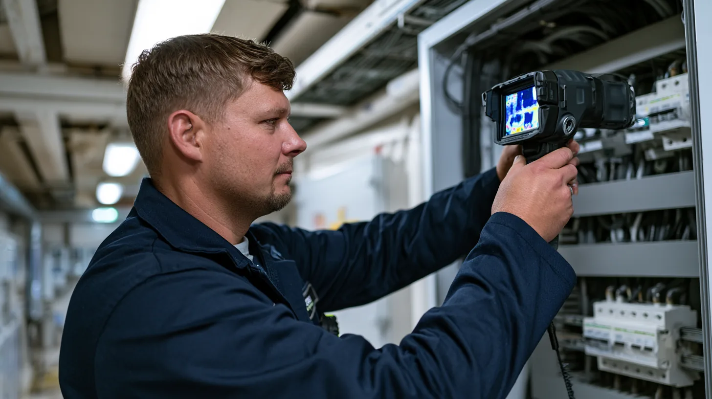
Infrared thermography: the highest-return complement
In value-for-money terms, the thermal imager is probably the best first predictive purchase a ship operator can make: immediate, non-intrusive, no shutdown required, and it produces an image any decision-maker understands without training.
Switchboards: the main source of findings
The great majority of detectable electrical faults begin as a connection heating up: a terminal loosened by hull vibration, oxidation in a salt-laden atmosphere, broken strands reducing effective section, a worn contactor, a fatigued fuse. A hot spot on one phase while the other two stay cool, under balanced load, is an almost certain diagnosis.
The non-negotiable condition: the board must be energised and under representative load — an unloaded inspection shows nothing. Hence a strict procedure: opening a live panel door, arc-rated PPE, the job restricted to the electro-technical officer (ETO) or the chief engineer depending on how the ship is organised, a second person present. These requirements are planned and recorded like any high-risk job (see our article on maintenance safety, lockout/tagout and authorisations). Permanently fitted infrared windows on main switchboard doors remove the hazard and make the thermal round almost trivial.
Bearings, heat exchangers, steam and exhaust lagging
- Bearings and couplings: a bearing running 15 to 20 °C above its symmetrical twin at equal load indicates a lubrication fault, excessive clearance or a bearing at end of life. The ideal cross-check against vibration analysis.
- Heat exchangers and coolers: thermal mapping instantly reveals fouled zones, blocked passes or partial scaling of a tube bundle. Cleaning is then planned on data rather than on the calendar.
- Steam lagging, exhaust manifolds, turbochargers: degraded insulation is visible immediately. Beyond the energy loss it is a major fire risk — a bare high-temperature exhaust surface meeting a fuel or lube oil leak remains a classic engine room fire scenario, and one flag State and class inspections routinely look for.
- Steam traps and valves: a trap stuck open or closed is identified from its upstream/downstream thermal signature, as is a valve passing internally.
Measurement precautions: emissivity, load, distance, reflections
A badly taken thermal image is worse than no measurement at all, because it provides false reassurance. Four traps dominate:
- Emissivity. A matt painted surface sits around 0.95; polished copper or bright stainless drops to 0.05–0.10 and returns an apparent temperature far below reality. On bare busbars, apply a patch of matt tape of known emissivity, or aim at the insulated part of the cable immediately adjacent.
- Load. Heat rise varies roughly with the square of the current. Record actual current and machine load at the time of the image: without it, no comparison between two campaigns is valid.
- Distance and field of view. If the target is smaller than the detector's instantaneous field of view, the camera averages target and surroundings and underestimates the hot spot. Get as close as safety allows, and never interpret a hot spot a few pixels across.
- Reflections. Sunlight, a halogen lamp, an operator in front of bright plating, a ventilation draught, rainwater on deck — all distort the reading. Move a few degrees: a reflection travels with you, a genuine hot spot stays put.
Criticality criteria
The right indicator is not absolute temperature but differential, measured against a similar component under the same conditions or against ambient. A robust decision grid, widely used across industry:
- 1 to 10 °C above reference: minor anomaly, log it and review at the next round.
- 10 to 20 °C: correction to be planned within the coming weeks.
- 20 to 40 °C: priority intervention, before any intensive operating period.
- Above 40 °C, or above the component's maximum rated temperature: immediate action, load reduction or isolation.
These thresholds are reference points to be adjusted against manufacturer guidance and criticality. What matters is that they are written down, known to everyone and tied to a defined action — not left to whoever happens to be on watch.
Shaft line and coupling alignment
Alignment is the highest-return and most neglected predictive technique: high return because good alignment removes the root cause of a large share of bearing and seal failures; neglected because it is seen as a yard operation when it is in fact a periodic check.
What misalignment costs
- Materially reduced bearing life — significant misalignment can halve theoretical life or worse.
- Premature wear of mechanical seals and stern gland packing, with recurrent leakage.
- Fatigue and overheating of flexible coupling elements, whose failure can be sudden.
- A few percent of extra energy consumption, imperceptible on one machine but significant across a fleet.
- On a propulsion shaft line: abnormal loading of the thrust bearing, stern tube and intermediate bearings, with risk of aft bearing overheating and shaft seal degradation.
Dial indicators or laser?
The dial indicator method — rim and face, or reverse dial radial readings — remains perfectly valid and costs almost nothing in equipment. It demands time, rigour in shim calculation, and remains sensitive to bracket sag: the classic error that silently invalidates a survey.
Laser systems cut setup time by half or two-thirds, calculate shims under each foot automatically, correct live while the machine is moved, handle soft foot and thermal growth, and generate a time-stamped report that can be archived. Across a fleet, one kit shared between several vessels with a trained operator on each works very well.
Three rules are non-negotiable in either case: check and correct soft foot before any alignment; target hot alignment rather than cold for machines that heat up; and take a confirmation vibration reading afterwards to validate the result objectively.
When to check
- After any removal and refit: electric motor, pump, gearbox, generator set.
- After a grounding, a touch-and-go, a berthing impact or any structural event — shaft line checks form part of the damage survey.
- After work on foundations, resilient mounts or chocking.
- At drydocking, bearing in mind that the hull deflects differently in dock and afloat — hence the value of a complementary afloat check under normal load for propulsion lines.
- As soon as the vibration signature shows a growing axial component at 2X. The ideal trigger: vibration tells you when to align, alignment removes the cause.
The trend matters far more than the single reading
A single reading of 4.2 mm/s says almost nothing: depending on the machine, its mounting and its speed, that level is either excellent or alarming. A machine that went from 1.8 to 4.2 mm/s in four months, on the same point under the same conditions, tells an unambiguous story. Three consequences:
- The first reading is a baseline signature. Take it on a healthy machine, after overhaul or at commissioning, and document it as such. Without a baseline, your first alarm arrives too late.
- Repeatability beats absolute accuracy. A moderately accurate reading always taken at the same point, on the same axis, at the same load, is worth more than a laboratory-grade measurement taken once a year under varying conditions.
- What counts is the slope. A value sitting stably above an alert threshold is often less urgent than one still below threshold but doubling every two months. Predictive maintenance is reading that slope to estimate when the critical threshold will be crossed, and intervening before.
Key takeaway. A vibration or thermal reading only has value when referenced to a baseline and a history. Three rules make the programme work: a fixed, physically marked measurement point; constant and recorded operating conditions; and a written threshold that automatically raises a work order. Without those three, you are collecting data. With them, you are doing predictive maintenance.
Organising a measurement round and wiring it into the PMS
Technique is never the limiting factor. What kills most predictive programmes is organisation: readings in a notebook or a spreadsheet living on the chief engineer's laptop, nobody analysing them, and a crew change that erases the ship's memory.
A measurement point is an asset, not a form field
Create each point as an object in its own right in the technical hierarchy, attached to its parent equipment. It carries a unique identifier (for example P-CIRC-01-BRG-FWD-H), a quantity, a unit, a described physical position, a measurement condition (load, speed), an interval, an alert threshold and an alarm threshold. Exactly the logic of a counter reading: a time-stamped value attached to an asset, accumulating over time.
Thresholds that trigger, not thresholds that decorate
- Alert threshold crossed: notification to the chief engineer, escalation to the fleet dashboard, creation of an investigation task — repeat reading within fifteen days, additional spectral analysis, thermal cross-check.
- Alarm threshold crossed: automatic generation of a high-priority work order, reservation of spares from stock, notification of the shore superintendent.
- In both cases the reading, the thermal image, the spectrum and the alignment report attach to the equipment history. That file, built up over time, makes a digital engine room log genuinely defensible in an audit, a class survey or an insurance claim.
A realistic round
On a medium-sized vessel, a well-designed monthly predictive round takes 90 to 120 minutes:
- Preparation (10 min): download the route to the mobile terminal — the application must work offline, since the engine room never has connectivity — check batteries, confirm the expected operating conditions are met.
- Thermal round (30 min): switchboards under load first, then bearings, heat exchangers, lagging, exhausts. One infrared and one visible image per point, with load recorded.
- Vibration round (45 min): critical machines first, points taken in fixed route order, noting every sensory anomaly — noise, smell, leak, heat by hand. The nose and ear of an experienced engineer remain first-class sensors.
- Close-out (15 min): synchronise on return to coverage, review exceedances, raise the associated work orders.
A mediocre programme executed every month for two years beats a perfect programme executed twice and then abandoned.
Ship, shore, contractor: who does what
The crew collects: they alone can measure under the right operating conditions, as often as required, with no mobilisation cost. Their scope: run the round, respect the points and conditions, report exceedances, carry out simple corrections (retightening, greasing, strainer cleaning, routine realignment where the officer is trained). Two to three days of training is enough for the collection level. Always train two officers: assigning the round to one individual means losing the know-how the day they sign off.
Shore — superintendent, technical department, Designated Person Ashore — analyses and arbitrates: set thresholds, consolidate fleet trends, compare sister vessels (a divergence between two identical ships is a very strong signal), decide budgets, coordinate spares supply through the purchasing module before urgency doubles the price, and guarantee documentary continuity between successive crews.
The specialist contractor handles difficult diagnosis and heavy technical work: in-depth spectral expertise, in-situ balancing, resonance investigation, full shaft line alignment, post-casualty survey. The right model is an annual or half-yearly visit by a certified analyst, prepared by shipboard data: he arrives with the history, targets the suspect machines and leaves a usable report. Without prior data the same visit costs two to three times more for a poorer outcome.
Which technique, for what, at what cost
| Technique | Target equipment | Typical interval | Faults detected | Entry cost (order of magnitude) |
|---|---|---|---|---|
| Vibration analysis (portable collector) | Pumps, fans, compressors, generator sets, gearboxes, electric motors | Monthly (critical) to half-yearly (standby) | Unbalance, misalignment, looseness, bearing defects (BPFO, BPFI, BSF, FTF), gear mesh, cavitation, resonance | EUR 3,000 to 15,000; 2 to 3 days of training |
| Infrared thermography | Switchboards, bearings, heat exchangers, lagging, exhausts, steam traps, batteries | Quarterly; monthly on critical switchboards | Loose connections, phase imbalance, exchanger fouling, degraded insulation, hot bearing, failed steam trap | EUR 1,500 to 8,000; 1 to 2 days of training |
| Laser shaft alignment | Motor-pump sets, motor-gearbox trains, generator sets, propulsion shaft lines | At every refit; annual check or at drydocking | Parallel and angular misalignment, soft foot, foundation deformation | EUR 5,000 to 20,000 (kit shareable across several vessels) |
| Oil and particle analysis | Main and auxiliary engines, gearboxes, hydraulic circuits, thrust bearing | Quarterly to half-yearly depending on running hours | Abnormal wear, water or fuel contamination, additive depletion, gear particles | EUR 30 to 120 per laboratory sample; onboard kits from EUR 1,000 |
| Performance monitoring (sensors, data bus, counters) | Propulsion, power generation, cooling, ventilation | Continuous, with monthly review | Efficiency drift, progressive fouling, excess consumption, load imbalance between machines | Low where the vessel is already instrumented; mainly software |
| Ultrasound inspection | Compressed air systems, steam traps, seals, slow-speed bearings | Half-yearly | Air and gas leaks, failed traps, lubrication faults, partial discharge | EUR 2,000 to 7,000 |
Sequencing advice for an operator starting out: begin with thermography, whose payback is fastest and most visual; add oil analysis, whose logistics are simple; bring in vibration analysis once round discipline is established; then laser alignment, shared across the fleet. Trying to deploy everything in the same quarter is the surest way to sustain none of it.
FAQ
Is certification required to carry out vibration analysis on board?
No certification is required by regulation to take condition monitoring readings. The professional framework ISO 18436 does define competence levels: category I covers data collection and comparison against thresholds, exactly the relevant scope for an engineer officer, and is acquired in two to three days. Categories II and III, covering in-depth spectral diagnosis and resonance analysis, belong to a specialist mobilised occasionally.
What vibration level should trigger an alert?
There is no universal figure. ISO 10816 / ISO 20816 define severity zones in mm/s according to machine power and mounting stiffness, which is a reasonable starting point. But the most reliable criterion on board remains deviation from the machine's own baseline signature: a doubling of the overall level at the same point under identical conditions justifies investigation, whatever the absolute value reached.
Can thermography replace vibration analysis?
No. Thermography sees the thermal consequences of a fault that is already advanced — a bearing running hot is a bearing already badly degraded — whereas vibration analysis, through acceleration enveloping, detects the same fault several months earlier. Conversely, thermography covers a whole domain vibration ignores: electrical connections, heat exchangers, lagging, steam traps. The two are complementary and validate each other.
At what fleet size does predictive maintenance pay off?
The question is not fleet size but equipment criticality and the cost of downtime. A single passenger vessel on a tight daily schedule justifies a full programme, because one cancelled rotation immediately costs more than the annual monitoring effort. Ten workboats with low downtime exposure will do perfectly well with a properly executed calendar-based programme. The decision threshold is economic, not quantitative, and it is assessed equipment by equipment.
What happens to accumulated readings at crew change?
That is exactly the problem a maintenance management system solves and a spreadsheet does not. Measurement points, reading conditions, thresholds, trends and past decisions must live in the ship's information system, available to the incoming crew from the day they join and to the shore superintendent at all times. A history stored on a personal laptop disappears at the first crew change, and two years of work with it.
How do you justify the investment to management?
With three figures, not with technical argument. The full cost of a typical casualty on the most critical item of equipment, including off-hire and substitute chartering. The annual cost of the programme: amortised hardware, training, crew time, the specialist's visit. And the number of casualties of that type across the fleet over the last three years — a figure your maintenance history should produce in minutes. The ratio between those three numbers wins the decision far more reliably than any explanation of bearing characteristic frequencies.
Conclusion
Predictive maintenance on board is not a technological leap; it is a measurement discipline. Three accessible techniques — vibration, thermography, alignment — cover most failure modes of a ship's rotating machinery, with no permanent instrumentation, no modification to the vessel, using the existing crew and a few days of training.
The real difficulty lies elsewhere: in the consistency of the round, the stability of measurement conditions, and the systematic link between a threshold exceedance and a work order actually raised, planned and closed. That is precisely what a marine maintenance management system delivers — turning a collection of values into traceable decisions, shared between ship and shore, and defensible before an auditor, a classification society or an insurer.
Smart Sailors treats measurement points as assets in their own right, historises readings, raises work orders on threshold crossing, and works offline in the engine room. Request a demonstration or start your 30-day free trial: your vessel's first predictive round can be scheduled this week.
These techniques deliver their full value once built into an overall plan, a subject we cover in the maritime CMMS guide.


.png)


